Felder dxf processor setup. To handle 3D configuration and 3d drawing in DXF.
Usefull files are here Manual and test files
Content of 3D.zip
select * from odzgon
Felder dxf processor setup. To handle 3D configuration and 3d drawing in DXF.
Usefull files are here Manual and test files
Content of 3D.zip
This is CNC program, which will create World.
As you can see you can change tool via pamameters.
Source of postprocessed file is here:
http://www.draftsperson.net/index.php?title=World_Map_-_Free_AutoCAD_DWG
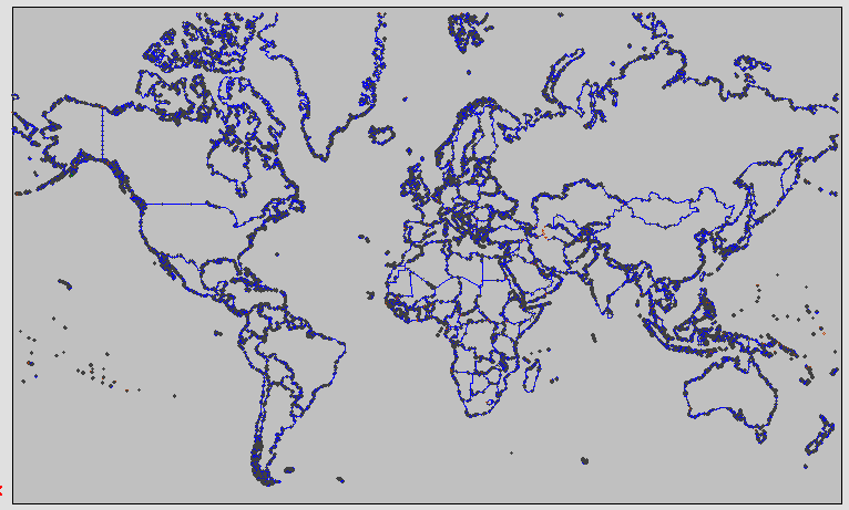
Generated file is here:
World Map with International borders
This is simple example how to use parametric programing for creating reusable programs.
Program is using 5-Motion Blade – 1236
And allow you to drill holes. You can control drilling with parmaters r3 where
0- dont do holes
1 – do holes at beginning of program
2 – do holes at end of program.
This allow you to make series of programs with only one change remove of 5-motion.
Note everythink is in Slovak language, but see this PDF for better understanding of parameters.
#0=400|dlzka medzistupna|r|f|

#1=90|uhol_lavy|w|f|

#2=90|uhol_pravy|w|f|

#3=0|Holes(0-NO,1-ONSTART,2-ONEND)|w|f|

#4=123456789|Cislo podstupnice|r|f|
Program is here:
uhlova_vrtanie.TCN
This is config example to TpaEdi32 Ver. 1.7.9 but it should work even on newer version of TpaEdit / WoodFlash.
Place file into following location (don’t forget to backup your file)
c:\WDFlash\CADCFG\CUSTOM\
Here you can download file. It’s ini file, this is why e.g. chrome tell about some security issiue. But it’s only text without any executable..
Sometimes you want to add pause into your program. Following line will do that:
W#102{ ::WTl #2=500 #3=10 #201=1 #205=1 #9505=97 }W
If you want add this line into your program, you can find it in
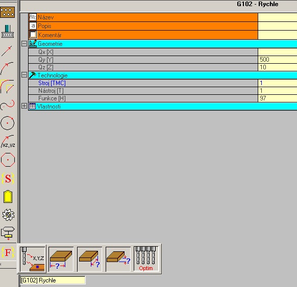
Be aware, that Qx,Qy,Qz are infomration where machine have to move and do pause. Then in woodflash you will have to comfirt pause is finished, program will contitnue with next step.
And this is how I use pause. As you can see I added pause after “hard” cut finish. Then in end of side 1. Becouse operator have to remove all part of material which can can make crash of side mill 🙂
1. Open DXF in TPAEDIT and generate TCN file
Editor will generate SETUPs and moves base on your drawing. You can remove / move lines in correct position on piece. SHIFT + LEFT MOUSE allow you to make selection of more part. When you finish save your file. Don’t use ” ” (space) in name of file. For example use name like Piece_1.tcn and save it in your working folder inside WDFlash e.g. c:\WDFlash\Product\DXF_TCN\ This will generate file c:\WDFlash\Product\DXF_TCN\Piece_1.tcn
2. Open TCN in text editor and create parametric TCN file
This step you can make in TPAEDIT but in text editor is much better choice. Open your file Piece_1.tcn and do following:
Add parameter definition and default values
Replace:
VAR{

}VAR
with this:
VAR{

#0=-10|Cut deep|w|f|cutdeep

#1=1001|Tool|w|f|tool

#2=0.5|Correction Offset (mm)|w|f|coroff

}VAR
Make SETUP – W#89 parametric:
Replace #3=0 #205=1001 #36=0.5 with #3=r0 #205=r1 #36=r2 in ALL lines which start with W#89. If #205=1001 #36=0.5 is missing in line just add them there.
e.g.
BEFORE:
W#89{ ::WTs WS=29  #1=511.364 #2=693.961 #3=0 #205=1001 #40=2 #36=0.5  #9510=0 }W

W#2201{ ::WTl  #8015=1 #1=-447.632 #2=0.0  }W

W#2201{ ::WTl  #8015=1 #1=877.418 #2=-100.594  }W
…
AFTER:
W#89{ ::WTs WS=29  #1=511.364 #2=693.961 #3=r0 #205=r1 #40=2 #36=r2 #9510=0 }W

W#2201{ ::WTl  #8015=1 #1=-447.632 #2=0.0  }W

W#2201{ ::WTl  #8015=1 #1=877.418 #2=-100.594  }W

...
Don’t forget to save your file.
3. Reopen file with TPAEDIT
If file is not loaded correctly you make something wrong 🙂 If you see your operation. Don’t forget to check tools corrections – if tool is moving on outside of profile. Save file.
4. Using parametric TCN in final program
Open new TCN file and add your Piece_1.tcn as subprogram. Set parameters for cutdeep (-12), tool (1001), correction(0.5). Repeat this step but set cutdeep (-24). Of course you can add addition, and change tool and correction as you want. Save file as e.g. Piece_FINAL.tcn
5. Reusing final program
Make copy of final program. Open program in text editor. Replace strong text.
W#2010{ ::WT2 WS=1 #8060=0 #8098=..\dxf_tcn\piece_1.tcn #8101=0 #8015=0 #8014=0 #8132=0 #8110=0 #8103=0 #8104=0 #8100=0 #8118=0 #8120=0 #8107=0 #8108=0 #8500=-12 #8501=1001 #8502=0.5 }W
#8098=..\dxf_tcn\piece_1.tcn can changed to point your new file e.g Piece_2.tcn (via step 1 and 2) #8098=..\dxf_tcn\piece_2.tcn
IMPORTANT
This is not best approche.
Some more information can by found here
http://press.odzgon.sk/felder-tpaedit-postprocessor/
Following post will put some light into tpaedit dxftocad processor. This convertor is used in Felder Group and allow user to load DXF file and generate TCN file. TCN file is specific NC file used by Albatros or whot ever…it contain code for machine.. code looks like this
SIDE#1{

W#89{ ::WTs WS=1 WN=1  #1=352.353 #2=0.0 #3=-8 #205=1001 #40=1 #36=7 #9510=1  }W

W#2201{ ::WTl  #8015=1 #1=0.0 #2=14.634  }W

W#2201{ ::WTl  #8015=1 #1=0.0 #2=30.366  }W

W#2201{ ::WTl  #8015=1 #1=-20.0 #2=0.0  }W

W#89{ ::WTs WS=2 WN=1  #1=352.353 #2=0.0 #3=-16 #205=1001 #40=1 #36=7 #9510=1  }W

W#2201{ ::WTl  #8015=1 #1=0.0 #2=14.634  }W

W#2201{ ::WTl  #8015=1 #1=0.0 #2=30.366  }W

W#2201{ ::WTl  #8015=1 #1=-20.0 #2=0.0  }W

W#89{ ::WTs WS=3 WN=1  #1=352.353 #2=0.0 #3=-8 #205=1001 #40=1 #36=0.5 #9510=1  }W

W#2201{ ::WTl  #8015=1 #1=0.0 #2=14.634  }W

W#2201{ ::WTl  #8015=1 #1=0.0 #2=30.366  }W

W#2201{ ::WTl  #8015=1 #1=-20.0 #2=0.0  }W
There is details and requirment for DXF to by converted as user want and minimalize manual/other changes of code.
DXF LAYER NAME -Base on layer name you can force some setup parametes e.g. PFT1001Z-8K2D1 means MILL SETUP Tool ID = 1001 Z = -8 Korecition = right with offset D = 1. This will generate SETUP with -8 as deep of cut.
POLYLINE – with correct LAYERNAME you can create working profile, Drawing order – vertex order is same like tool move.
POLILINE with Thickness -Must have some LAYER NAME. Remove Z parameter. Thicness allow to control depth of cut.
3DPLINE – Same like POLYLINE, but remove Z parameter and must change configuratio of to DXF to use 3D coord
BLOCKS – Block name is is used to call subprogram. First setup point in subprogram should by used as BLOCK reference point. You can select r0,r1… parameters via adding attribude (max 26, atribute name should by one char “T” ..) to block. Number 8500 = r0
I DONT FIND WAY HOW TO CHANGE WORK ORDER ENTITIES ARE CUTTED IN SAME ORDER HOW YOU DRAW THEM